


Thank you for your purchase of Kondex KX7 concaves! With each concave, you should have received a printed version of these installation instructions, hardware to mount the concaves, and hardware to bolt the KX7 frames together (where applicable).
The items below are what you will need for KX7 concave installation.
- Installation instructions
- Hardware for bolting concaves together (for complete kits and ThreshStartTM kits, you will have extra hardware)
- Hardware for mounting concaves in combine
 Concave assemblies are heavy and awkward to handle. Another person may be needed to remove and install concave assemblies.
KX7 Recommendations
Settings and Maintenance
KX7 Setting Recommendations
Note: setting recommendations provided assume all other combine settings are adjusted accordingly and functioning properly.
- Reference all combine settings in your combine owner’s manual specific to the crops you are harvesting.
- All concave and rotor speed adjustment logic remains the same. Recommendations below represent what has been used in the field across different crops and conditions. Note: harvesting conditions can drastically change these recommendations.
- Concave Clearance: Typically, KX7 users harvest 1-5 more open on concave clearance than they ran with OEM concaves, specific to the crop being harvested.
- Conditions can significantly change this setting recommendation.
- If you were not previously running OEM concaves (rather using other aftermarket concaves), these reference points may not be valid.
- Rotor Speed: Typically, KX7 users can run on the lower end of recommended rotor speed, specific to the crop being harvested.
- Conditions can significantly change this setting recommendation.
- If you were not previously running OEM concaves (rather using other aftermarket concaves), these reference points may not be valid.
KX7 Maintenance Recommendations
Prior to operation, inspect concaves for damaged boxes, loose or missing hardware, or excessive wear. If you notice any of these issues, correct as needed to maintain optimal performance.
Installation Instructions by Make
AGCO Combines
KX7 Installation Instructions
- Reference all concave removal and installation procedures in your combine owner’s manual.
- In your combine owner’s manual, locate and turn to the concave removal section.
- Remove current concaves from the combine, following concave removal procedures in your combine owner’s manual.
- Install concaves in the configuration matching the KX7 kit that was ordered, typically MaxThreshTM concaves are in the front position(s) followed by MaxRoundTM concaves (See Figure 1).
(Note: configurations may vary depending on region, crop conditions, and dealer recommendations.)FIGURE 1
- Follow concave installation procedures in your combine owner’s manual.
- Loosely assemble hardware to mounting brackets. These will be tightened after all KX7 concaves are installed.
- Tighten all mounting hardware and torque to 53 N•m (39 ft-lb).
- Once KX7 concaves are installed, level and zero your concaves following the procedures in your combine owner’s manual.
- Reference your owner’s manual to confirm that you have completed all steps after concave installation.
Individual Box Insert Replacement
If individual box insert replacement is desired, first remove the original KX7 insert(s). Set the new KX7 box(es) in place and tighten/torque the new hardware to 53 N•m (39 ft-lb).
Case IH Flagship Combines
KX7 Installation Instructions
- Reference all concave removal and installation procedures in your combine owner’s manual.
- In your combine owner’s manual, locate and turn to the concave removal section.
- Remove current concaves from the combine, following concave removal procedures in your combine owner’s manual.
- Each removed concave will be replaced with two half-width KX7 concaves. Locate left- and right-hand concaves for installation accordingly.
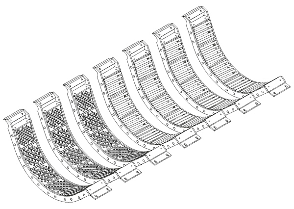
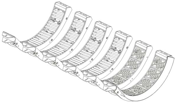
- Install concaves in the configuration matching the KX7 kit that was ordered, typically MaxThreshTM concaves are in the front position(s) followed by MaxRoundTM concaves (See Figures 2a and 2b).
(Note: configurations may vary depending on region, crop conditions, and dealer recommendations.)FIGURE 2A (models requiring front ramp)
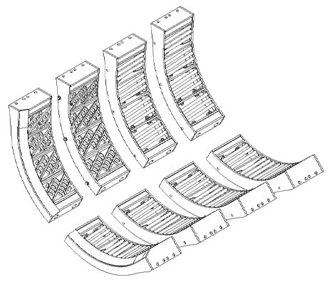
FIGURE 2B (models not requiring front ramp)
- Follow concave installation procedures in your combine owner’s manual. (Note: two KX7 concaves will need to be installed for each single OEM concave removed.)
- Loosely assemble hardware to mounting brackets. These will be tightened after step 6.
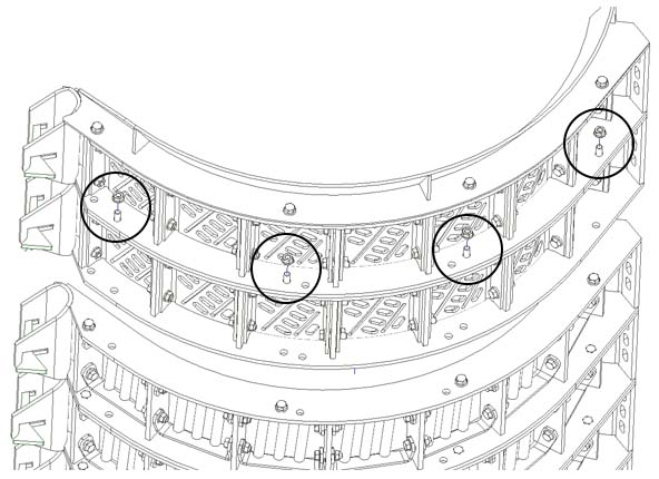
- Once all KX7 concaves are installed in the combine, use the holes along the radius of the frames and the hardware provided to loosely assemble the concave frames together (hardware provided in a zip-top bag).
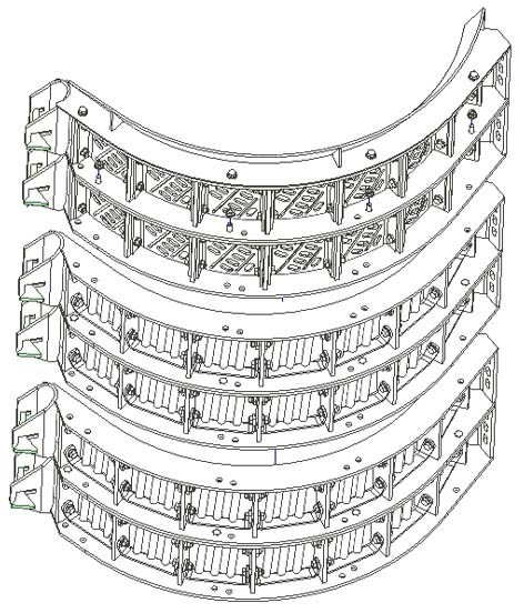
- Assemble the two concaves in each module position together (See Figures 3a and 3b).
FIGURE 3A (models requiring front ramp)
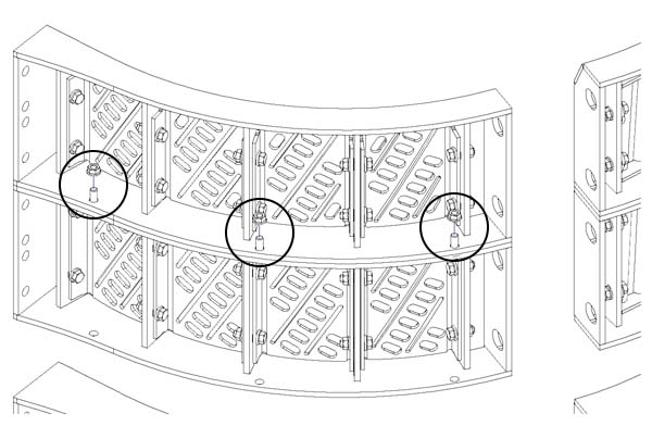
FIGURE 3B (models not requiring front ramp)
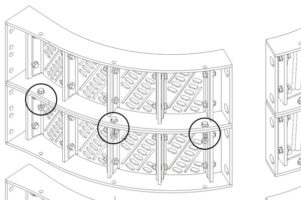
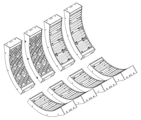
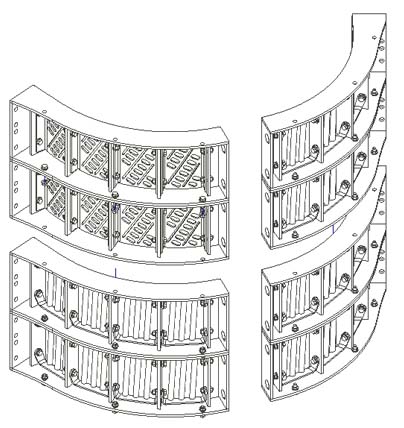
- Concave assemblies should now mimic OEM concave configuration (See Figures 4a and 4b).
FIGURE 4A (models requiring front ramp)
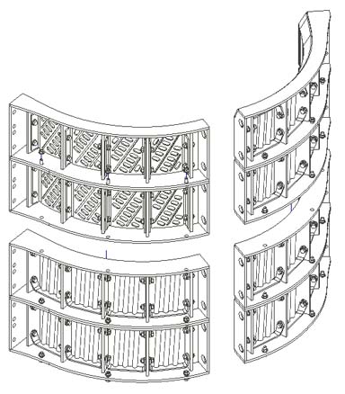
FIGURE 4B (models not requiring front ramp)
- Assemble the two concaves in each module position together (See Figures 3a and 3b).
- Tighten all mounting hardware (Steps 5 and 6) and torque to 53 N•m (39 ft-lb).
- Once KX7 concaves are installed, level and zero your concaves following the procedures in your combine owner’s manual.
- Reference your owner’s manual to confirm that you have completed all steps after concave installation.
Individual Box Insert Replacement
If individual box insert replacement is desired, first remove the original KX7 insert(s). Set the new KX7 box(es) in place and tighten/torque the new hardware to 53 N•m (39 ft-lb).
Case IH Mid-Series Combines
KX7 Installation Instructions
- Reference all concave removal and installation procedures in your combine owner’s manual.
- In your combine owner’s manual, locate and turn to the concave removal section.
- Remove current concaves from the combine, following concave removal procedures in your combine owner’s manual.
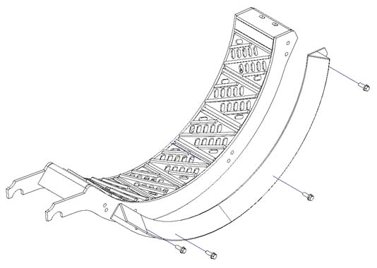
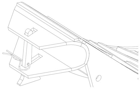
- Each removed concave will be replaced with two half-width KX7 concaves. Install front ramp on the front-position concave (See Figure 5).
FIGURE 5
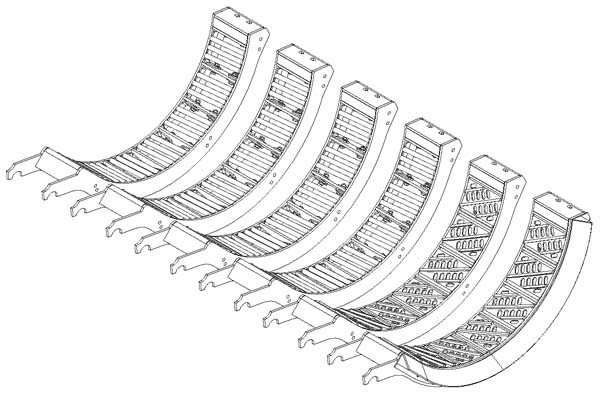
- Install concaves in the configuration matching the KX7 kit that was ordered, typically MaxThreshTM concaves are in the front position(s) followed by MaxRoundTM concaves (See Figure 6).
(Note: configurations may vary depending on region, crop conditions, and dealer recommendations.)FIGURE 6
- Follow concave installation procedures in your combine owner’s manual. (Note: two KX7 concaves will need to be installed for each single OEM concave removed.)
- Loosely assemble hardware to mounting brackets. These will be tightened after step 6.
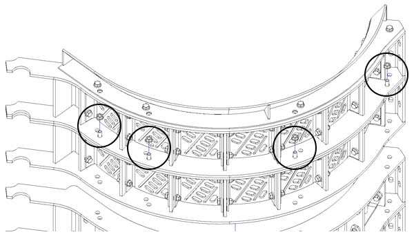
- Once all KX7 concaves are installed in the combine, use the holes along the radius of the frames and the hardware provided to loosely assemble the concave frames together (hardware provided in zip-top bag).
- Assemble concave one to two, three to four, and five to six (See Figure 7).
FIGURE 7
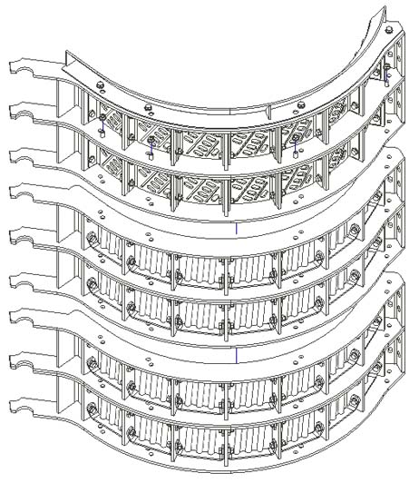
- Concave assemblies should now mimic OEM concave configuration (See Figure 8).
FIGURE 8
- Assemble concave one to two, three to four, and five to six (See Figure 7).
- Tighten all mounting hardware (Steps 5 and 6) and torque to 53 N•m (39 ft-lb).
- Once KX7 concaves are installed, level and zero your concaves following the procedures in your combine owner’s manual.
- Reference your owner’s manual to confirm that you have completed all steps after concave installation.
Individual Box Insert Replacement
If individual box insert replacement is desired, first remove the original KX7 insert(s). Set the new KX7 box(es) in place and tighten/torque the new hardware to 53 N•m (39 ft-lb).
Fendt Ideal Combines
KX7 Installation Instructions
- Reference all concave removal and installation procedures in your combine owner's manual.
- In your combine owner's manual, locate and turn to the concave removal section
- Remove current concaves from the combine, following concave removal procedures in your combine owner's manual.
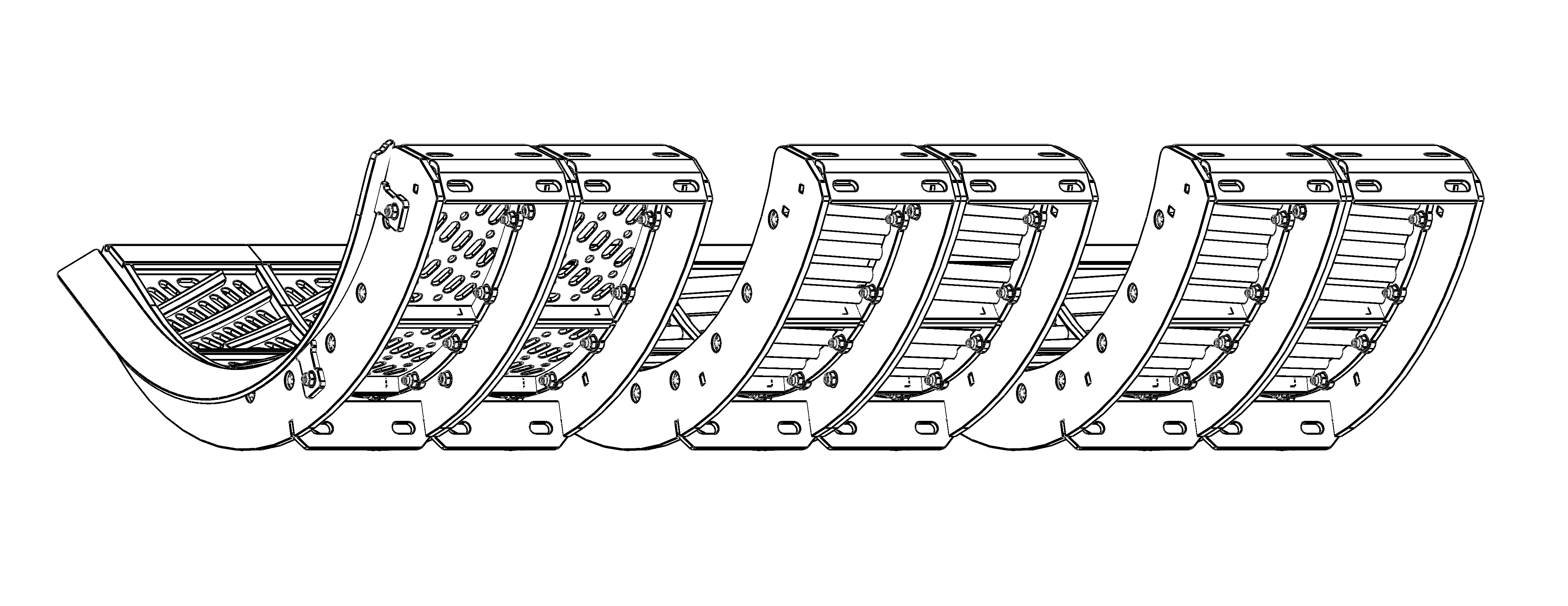
- Install concaves in the configuration matching the KX7 kit that was ordered, typically MaxThresh™ concaves are in the front position(s) followed by MaxRound™ concaves (See Figure 9). Ensure proper left-hand versus right-hand orientation (See Figure 10).
(Note: configurations may vary depending on region, crop conditions, and dealer recommendations.)
FIGURE 9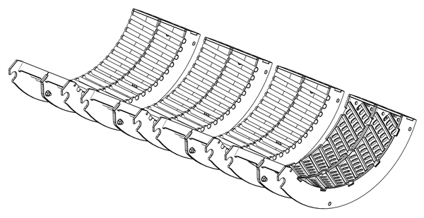
FIGURE 10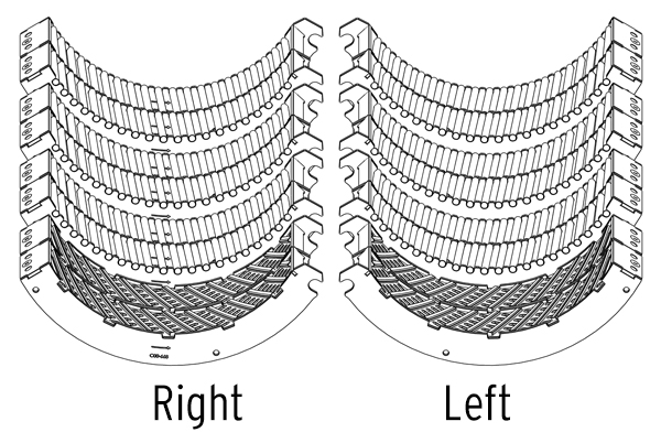
a. Follow concave installation procedures in your combine owner's manual.
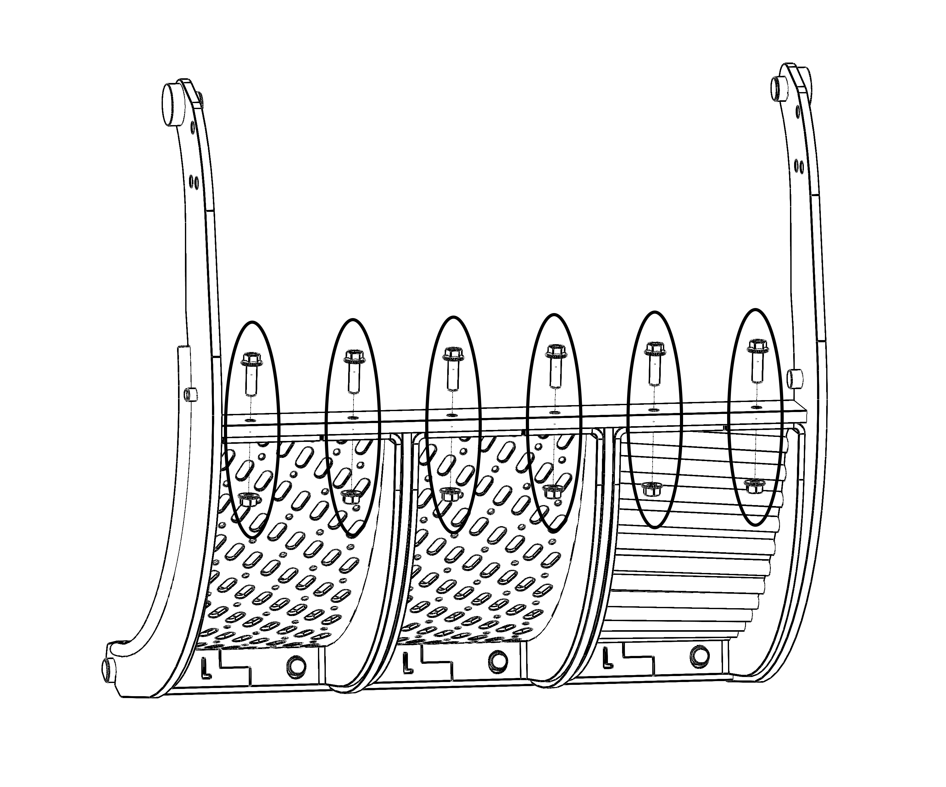
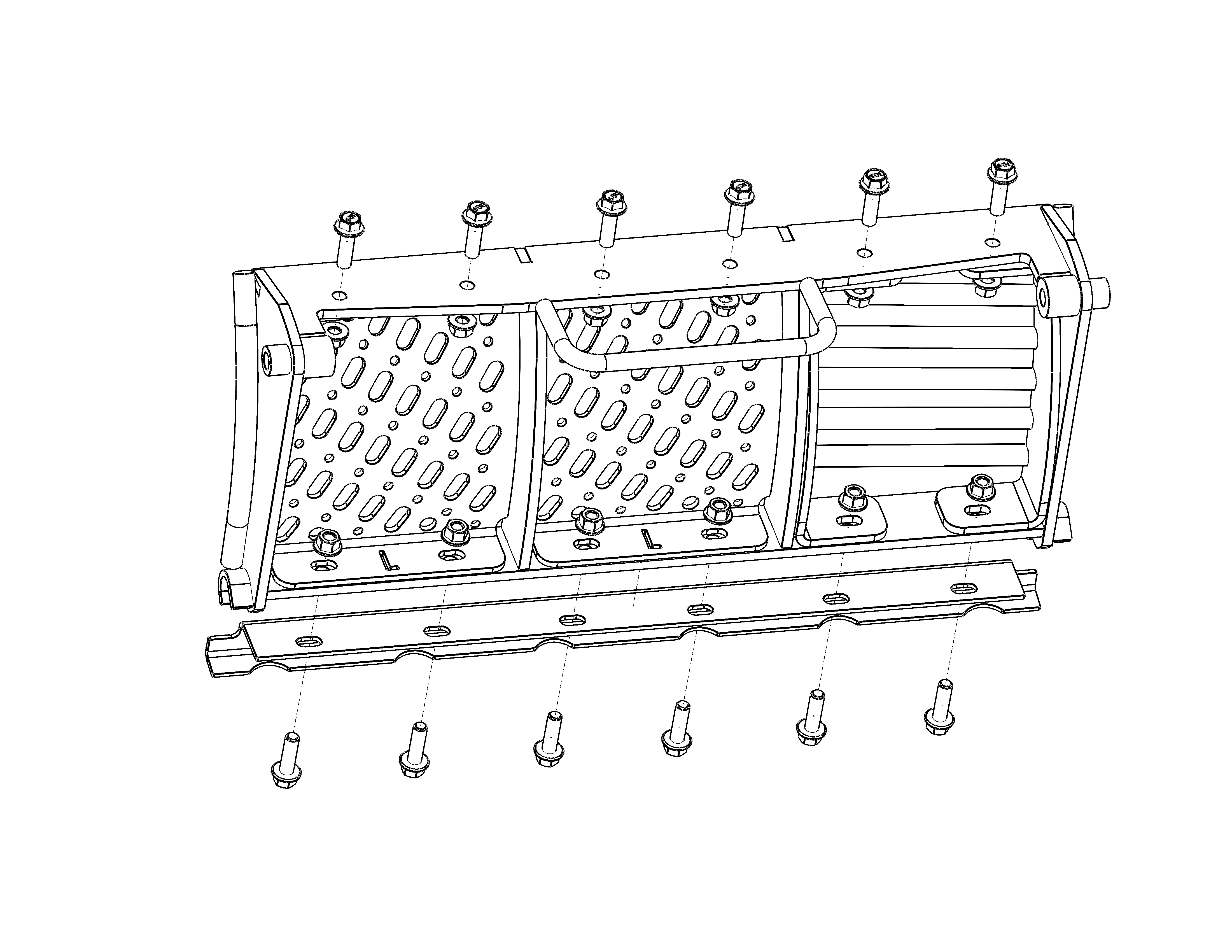
b. Loosely assemble (2) M16 bolts and (2) lock washers per concave to combine side rail (See Figure 11).
FIGURE 11
5. Tighten M16 hardware securing concave to side rail. Torque to 275 N•m (200 ft-lb).
6. Once KX7 concaves are installed, level and zero your concaves following the procedures in your combine owener's manual.
7. Reference your owner's manual to confirm that you have completed all steps after concave installation.
Front/Rear Assembly Replacement
If front and rear concave assemblies are split and need to be refastened, tighten bolts to 52 N•m (38 ft-lb).
Installation Tips
Prior to removing existing concaves, be aware of which side of the concave frame the MADS sensor is located.
For easier installation, place a sheet of plywood or other substrate below the concaves.
John Deere STS & S-Series Combines
KX7 Installation Instructions
- Reference all concave removal and installation procedures in your combine owner’s manual.
- In your combine owner’s manual, locate and turn to the concave removal section.
- Remove current concaves from the combine, following concave removal procedures in your combine owner’s manual.
- Each removed concave will be replaced with two half-width KX7 concaves.
- Install front ramp on the front-position concave (See Figure 12).
FIGURE 12
- Remove hanger pins prior to installation (See Figure 13).
FIGURE 13
- Install front ramp on the front-position concave (See Figure 12).
- Install concaves in the configuration matching the KX7 kit that was ordered, typically MaxThreshTM concaves are in the front position(s) followed by MaxRoundTM concaves (See Figure 14).
(Note: configurations may vary depending on region, crop conditions, and dealer recommendations.)FIGURE 14
- Follow concave installation procedures in your combine owner’s manual. (Note: two KX7 concaves will need to be installed for each single OEM concave removed.)
- Install hanger pins once concaves are in place (See Figure 15).
FIGURE 15
- Loosely assemble hardware to mounting brackets. These will be tightened after step 6.
- Once all KX7 concaves are installed in the combine, use the holes along the radius of the frames and the hardware provided to loosely assemble the concave frames together (hardware provided in zip-top bag).
- Assemble concave one to two, three to four, and five to six (See Figure 16).
FIGURE 16
- Concave assemblies should now mimic OEM concave configuration (See Figure 17).
FIGURE 17
- Assemble concave one to two, three to four, and five to six (See Figure 16).
- Tighten all mounting hardware (Steps 5 and 6) and torque to 53 N•m (39 ft-lb).
- Once KX7 concaves are installed, level and zero your concaves following the procedures in your combine owner’s manual.
- Reference your owner’s manual to confirm that you have completed all steps after concave installation.
Individual Box Insert Replacement
If individual box insert replacement is desired, first remove the original KX7 insert(s). Set the new KX7 box(es) in place and tighten/torque the new hardware to 53 N•m (39 ft-lb).
John Deere X-Series Combines
KX7 Installation Instructions
- Reference all concave removal and installation procedures in your combine owner’s manual.
- In your combine owner’s manual, locate and turn to the concave removal section.
- Remove current concaves from the combine, following concave removal procedures in your combine owner’s manual.
Sequencing Suggestion:- Remove the rear position concave(s).
- Remove the middle position concave(s).
- Install the two half-width KX7 concaves planned for the rear position (typically MaxRoundTM concaves). This sequence will maintain the position of the z-bar by always having one concave installed; whereas, removing all concaves at the same time can create difficulty in z-bar realignment and concave installation.
- Remove the front position concave.
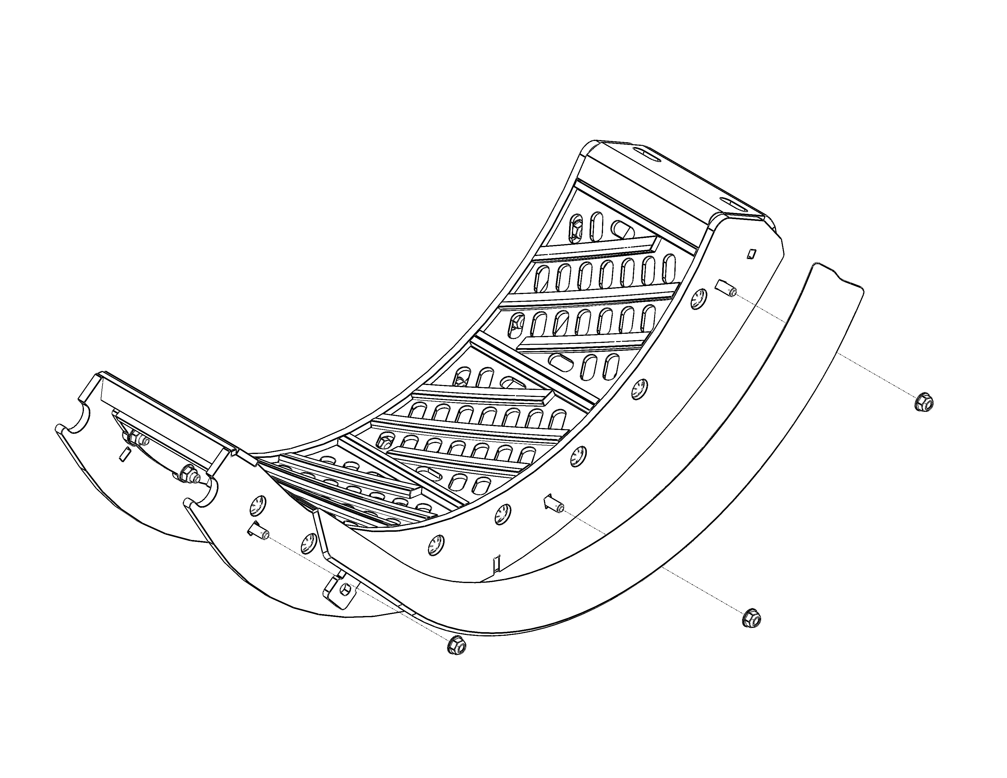
- Remove the front ramp from the removed front concave and attach it to the KX7 front-position concave (new front ramps not provided with KX7 concaves) (See Figure 18). Torque nuts to 40 N•m (30 ft-lb).
- Install the two half-width KX7 concaves with front ramp into the front position.
- Install the two half-width KX7 concaves into the middle position.
FIGURE 18
- Install concaves in the configuration matching the KX7 kit that was ordered, typically MaxThreshTM concaves are in the front position(s) followed by MaxRoundTM concaves (See Figure 19). Ensure proper left-hand versus right-hand orientation (See Figure 20).
(Note: configurations may vary depending on region, crop conditions, and dealer recommendations.)- Follow concave installation procedures in your combine owner’s manual.
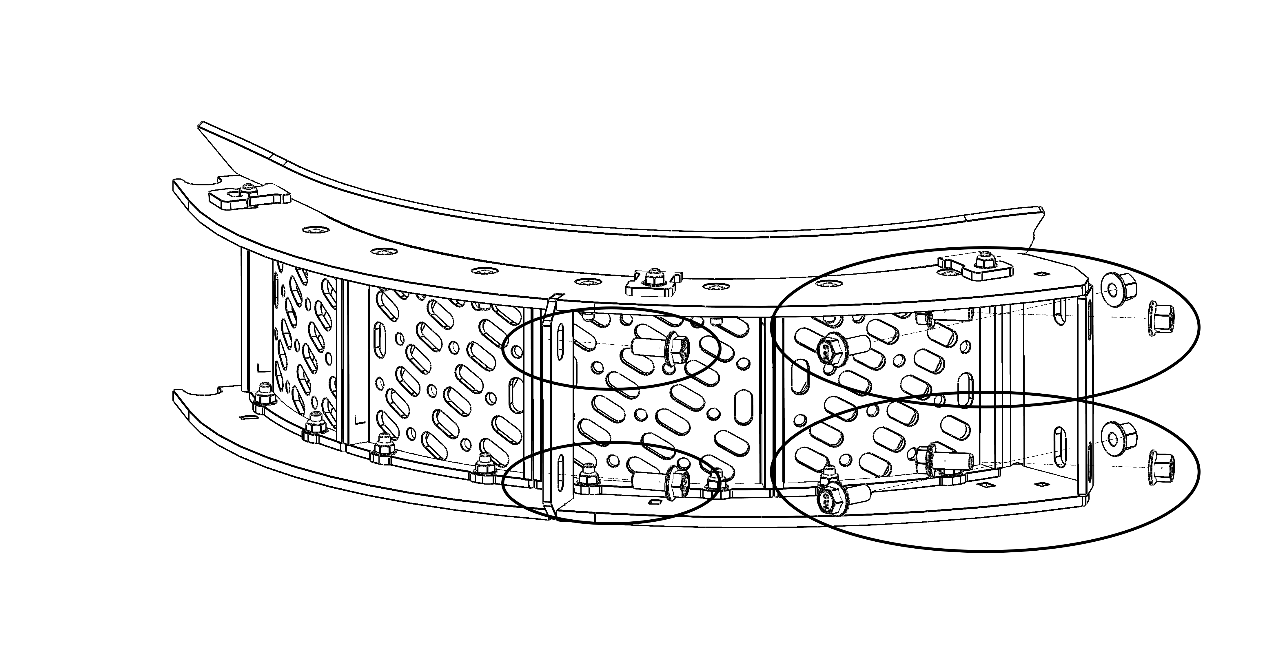
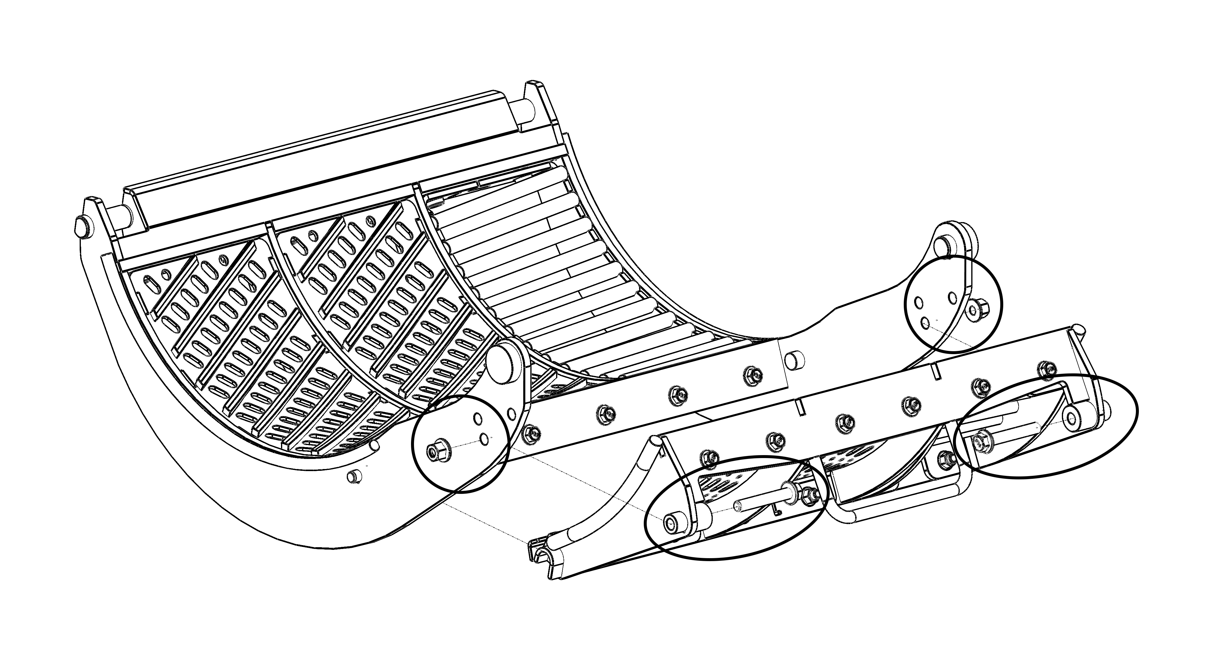
- Loosely assemble (2) M12 bolts per concave to captive nuts in OEM carrier frame (See Figure 21).
- Loosely assemble (4) M12 bolts and nuts per concave to combine z-bar weldment (See Figure 21).
- Hardware will be tightened after step 6.
FIGURE 19
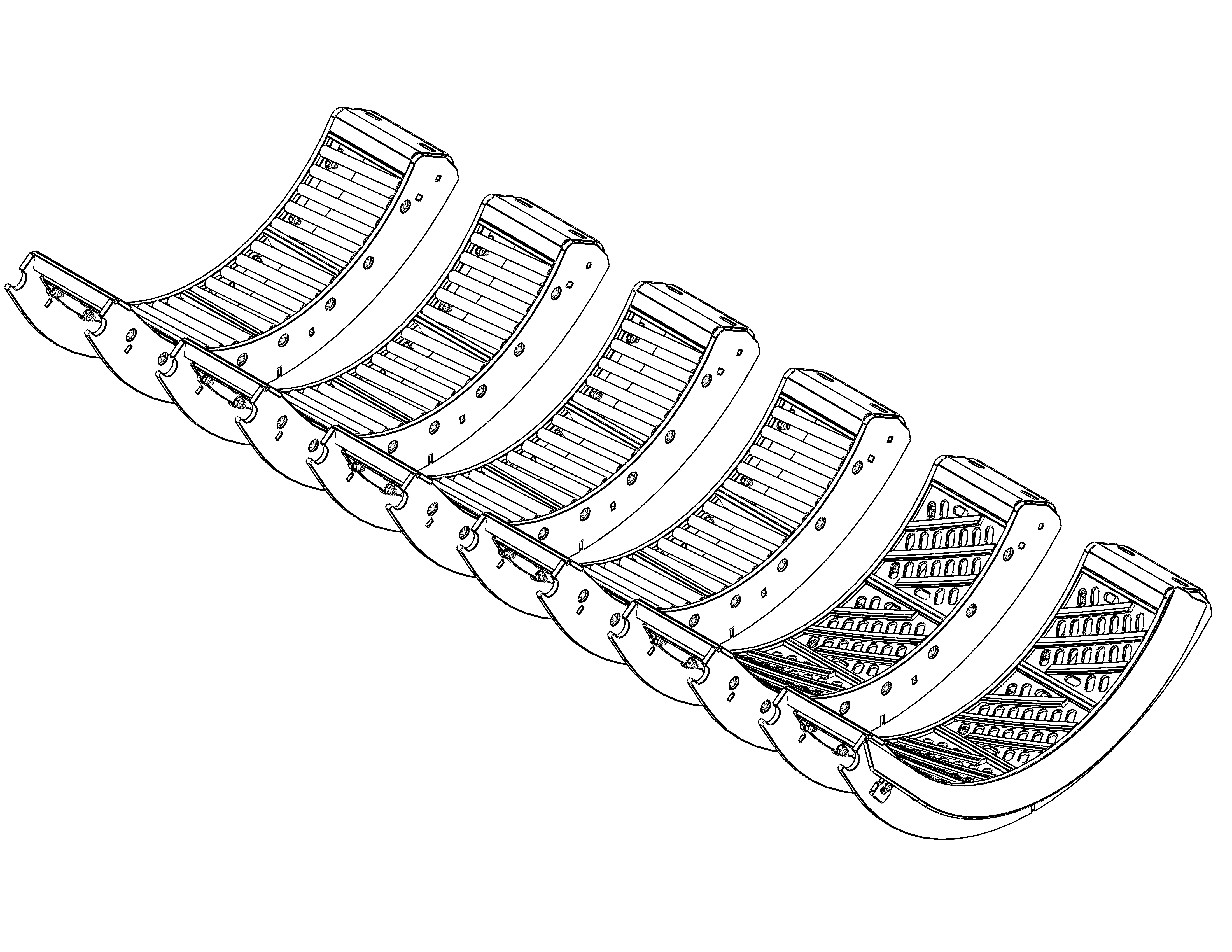
FIGURE 20
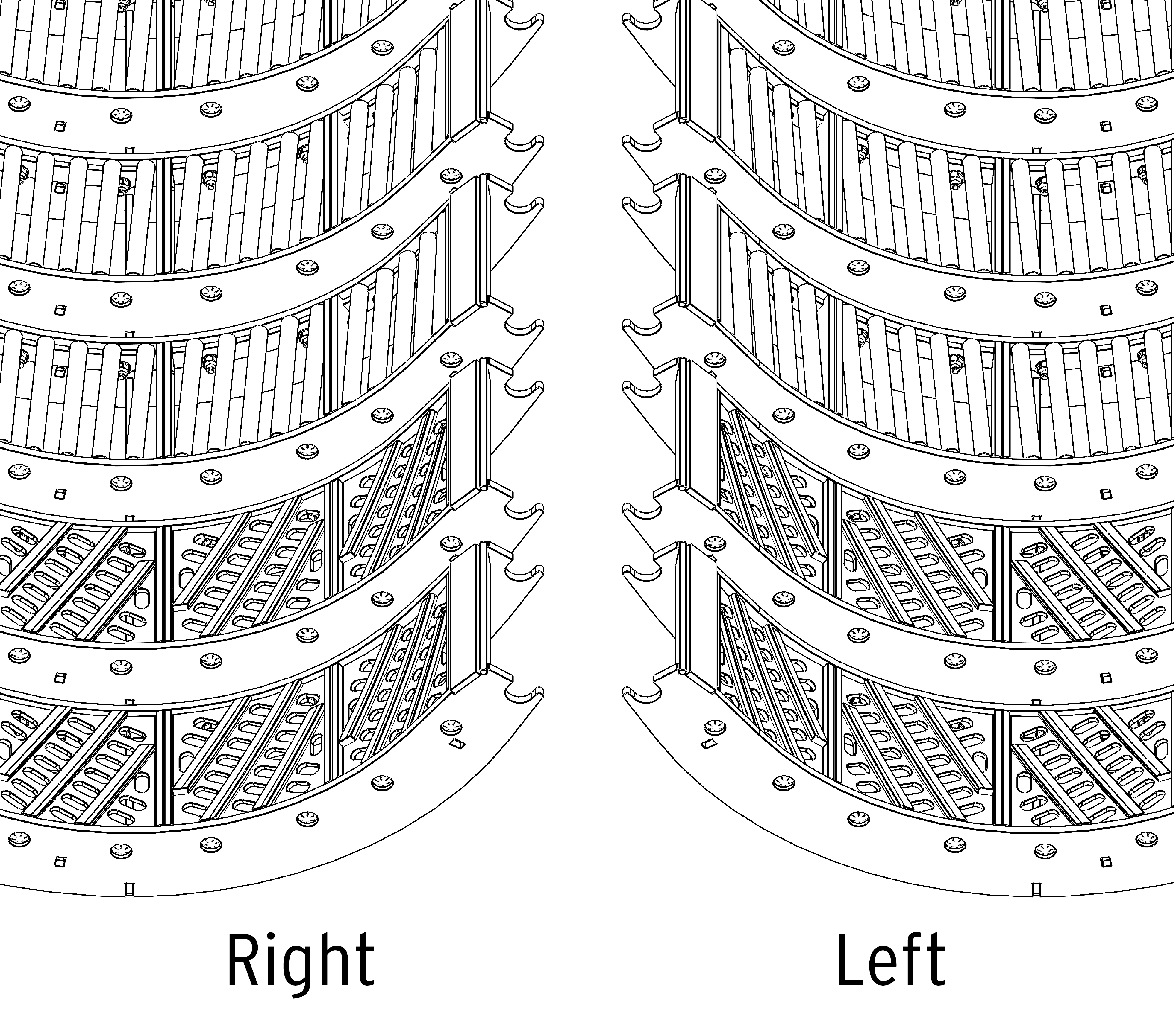
FIGURE 21
- Once all KX7 concaves are installed in the combine, use the holes along the radius of the frames and the hardware provided to loosely assemble the concave frames together (hardware provided in zip-top bag).
- Assemble concave one to two, three to four, and five to six (See Figure 22).
- Concave assemblies should now mimic OEM concave configuration (See Figure 23).
FIGURE 22
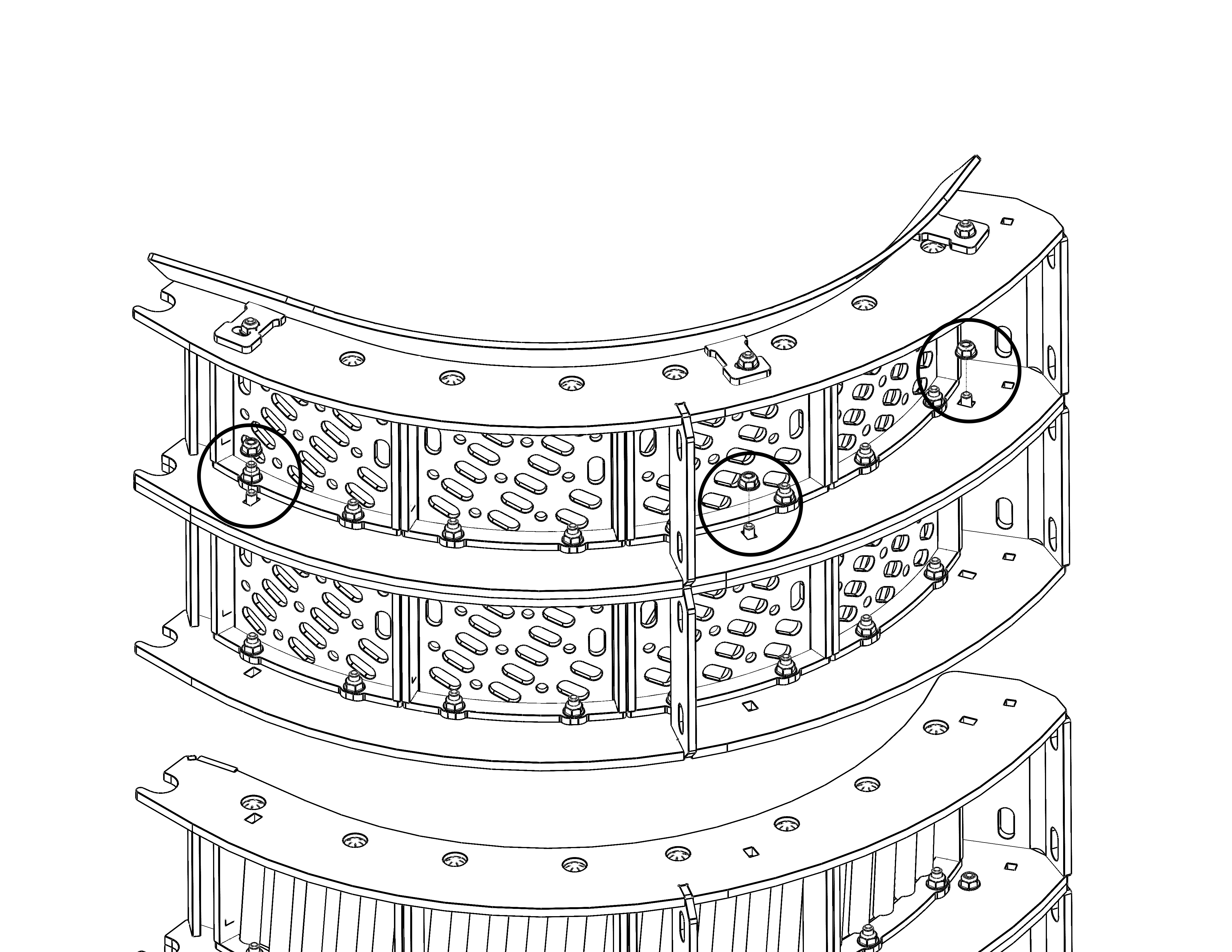
FIGURE 23
- Tighten 5/16” hardware securing concaves to each other (Step 5) and torque to 40 N•m (30 ft-lb).
- Tighten M12 hardware securing concave to carrier frame and z-bar weldment (Step 4). Torque to 97 N•m (72 ft-lb).
- Once KX7 concaves are installed, level and zero your concaves following the procedures in your combine owner’s manual.
- Reference your owner’s manual to confirm that you have completed all steps after concave installation.
Individual Box Insert Replacement
If individual box insert replacement is desired, first remove the original KX7 insert(s). Set the new KX7 box(es) in place and tighten/torque the new hardware to 40 N•m (30 ft-lb).
New Holland CR-Series Combines
KX7 Installation Instructions
- Reference all concave removal and installation procedures in your combine owner’s manual.
- In your combine owner’s manual, locate and turn to the concave removal section.
- Remove current concaves from the combine, following concave removal procedures in your combine owner’s manual.
- Kondex recommends the KX7 frame be installed in the combine prior to installation of individual box inserts. Follow the frame installation procedures in your combine owner’s manual.
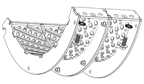
- Assemble individual box inserts into the main KX7 concave frame in the desired configuration. Typically MaxThreshTM concaves are in the front position(s) followed by MaxRoundTM concaves (See Figure 24). Ensure the proper left and right orientation, as indicated by the cutout on each box (See Figure 25). Torque M10 bolts and nuts to 74 N•m (55 ft-lb).
FIGURE 24
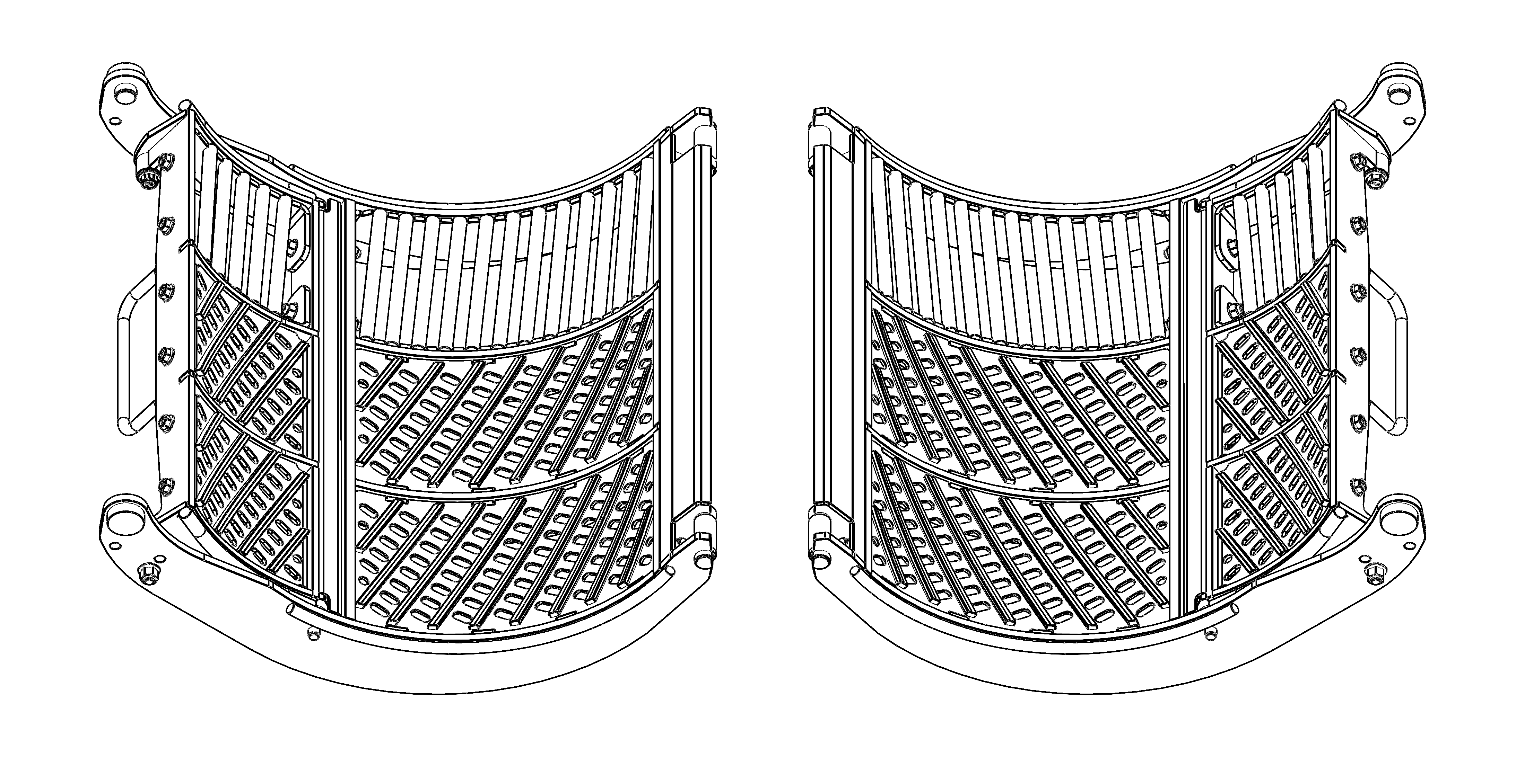
FIGURE 25
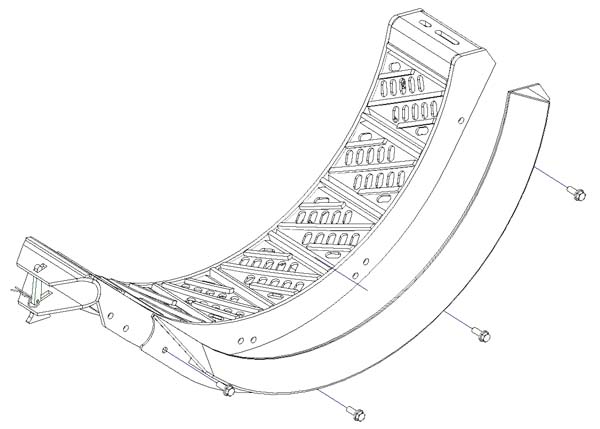
- Assemble individual box inserts into the adjustable KX7 concave frame in the desired configuration. Ensure the retainer is in place on the underside of the adjustable frame, and again ensure proper left and right orientation (See Figure 26). Torque M10 bolts and nuts to 74 N•m (55 ft-lb).
FIGURE 26
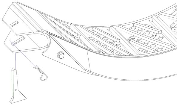
- Install the adjustable KX7 frame to the main KX7 frame in the desired location (See Figure 27). Torque M12 bolts and nuts to 97 N•m (72 ft-lb).
FIGURE 27
- Once KX7 concaves are installed, level and zero your concaves following the procedures in your combine owner’s manual.
- Reference your owner’s manual to confirm that you have completed all steps after concave installation.
Individual Box Insert Replacement
If individual box insert replacement is desired, first remove the original KX7 insert(s). Set the new KX7 box(es) in place and tighten/torque the new hardware to 74 N•m (55 ft-lb).